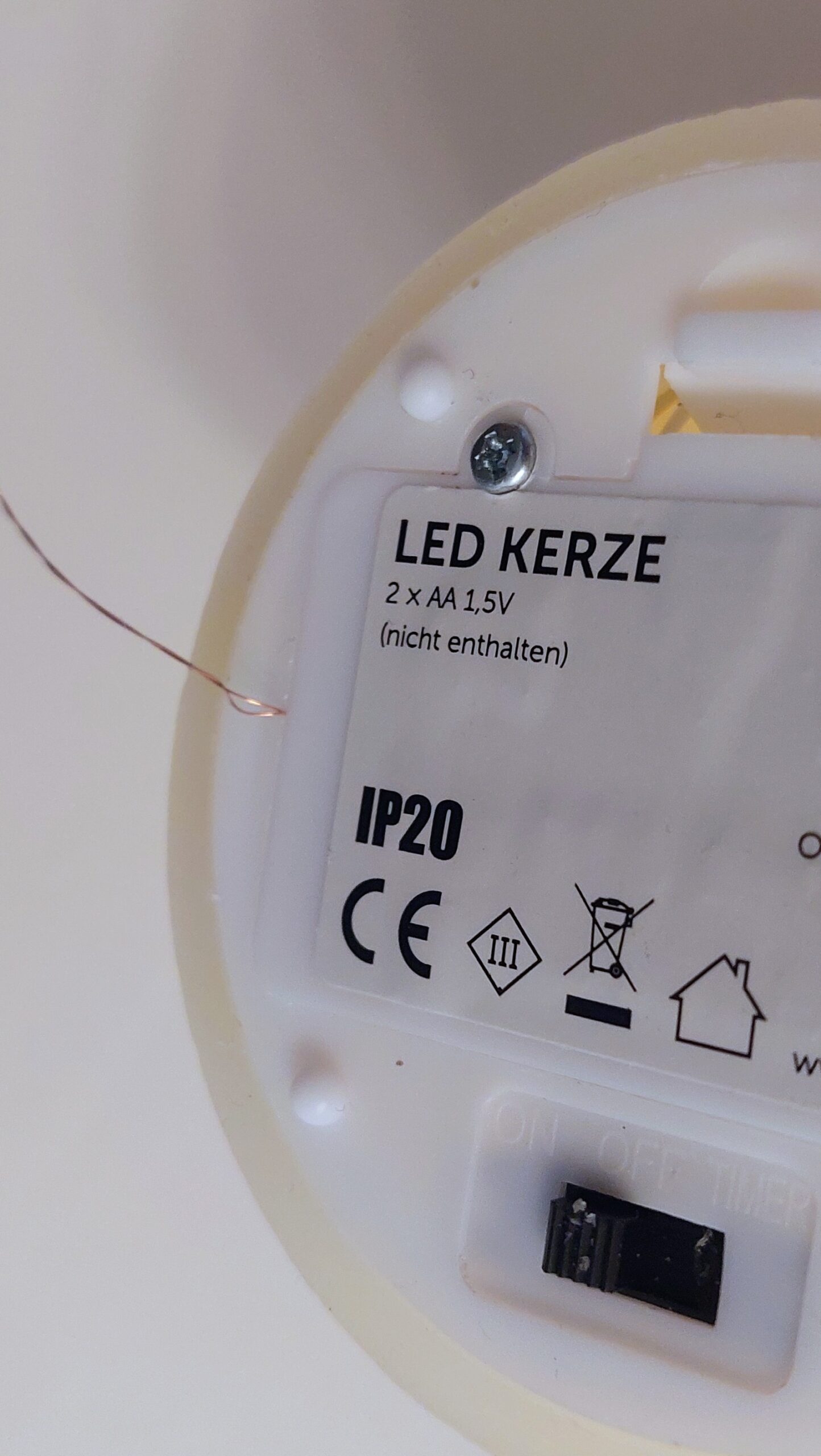
I recently picked up a set of four realistic LED wax candles – they flicker nicely and really look like the real thing. Cost? A whopping € 9,95 for the set of four. The downside: they aren’t smart, and each candle runs on 2 × 1.5 V AA batteries – that’s 8 batteries in total for my set.

A friend got me thinking: why not make them smart? I decided to give my candles a smart upgrade for the Advent season. Here’s a quick run-through of how I did it.
Turning Candles Smart with D1 Mini and ESPHome
To make the candles controllable from your phone, I used a D1 Mini with ESPHome integrated into Home Assistant. This setup lets you:
- Switch each candle individually without touching them
- Avoid handling 8 batteries every time
- Control brightness and even create a sequence – light one candle per Advent, if you like
Each candle gets its own GPIO pin. The D1 Mini handles the logic, while ESPHome exposes each candle as a switch in Home Assistant.
Battery Dummy
Instead of buying a commercial AA battery dummy, you can easily create one yourself at very low cost. I used a hardwood round dowel with the same diameter as an AA cell and cut it to the exact AA length, including the small height difference of the positive terminal. After cutting, I drilled a small pilot hole into each end to host the contacts.

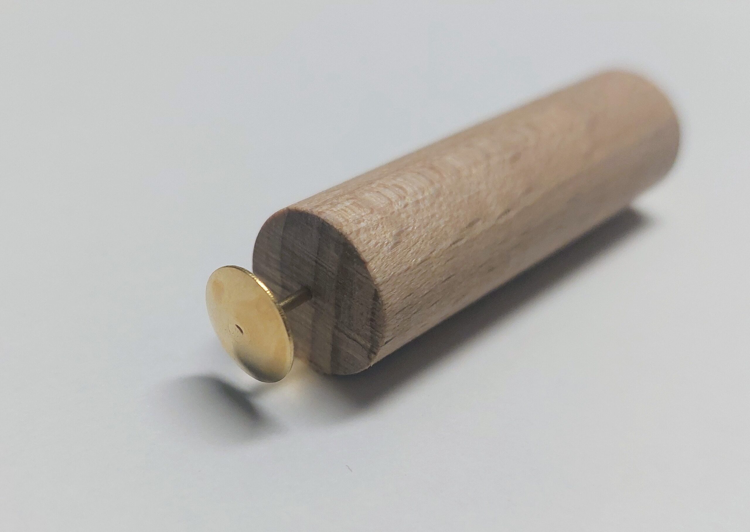

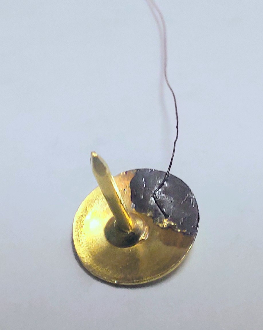
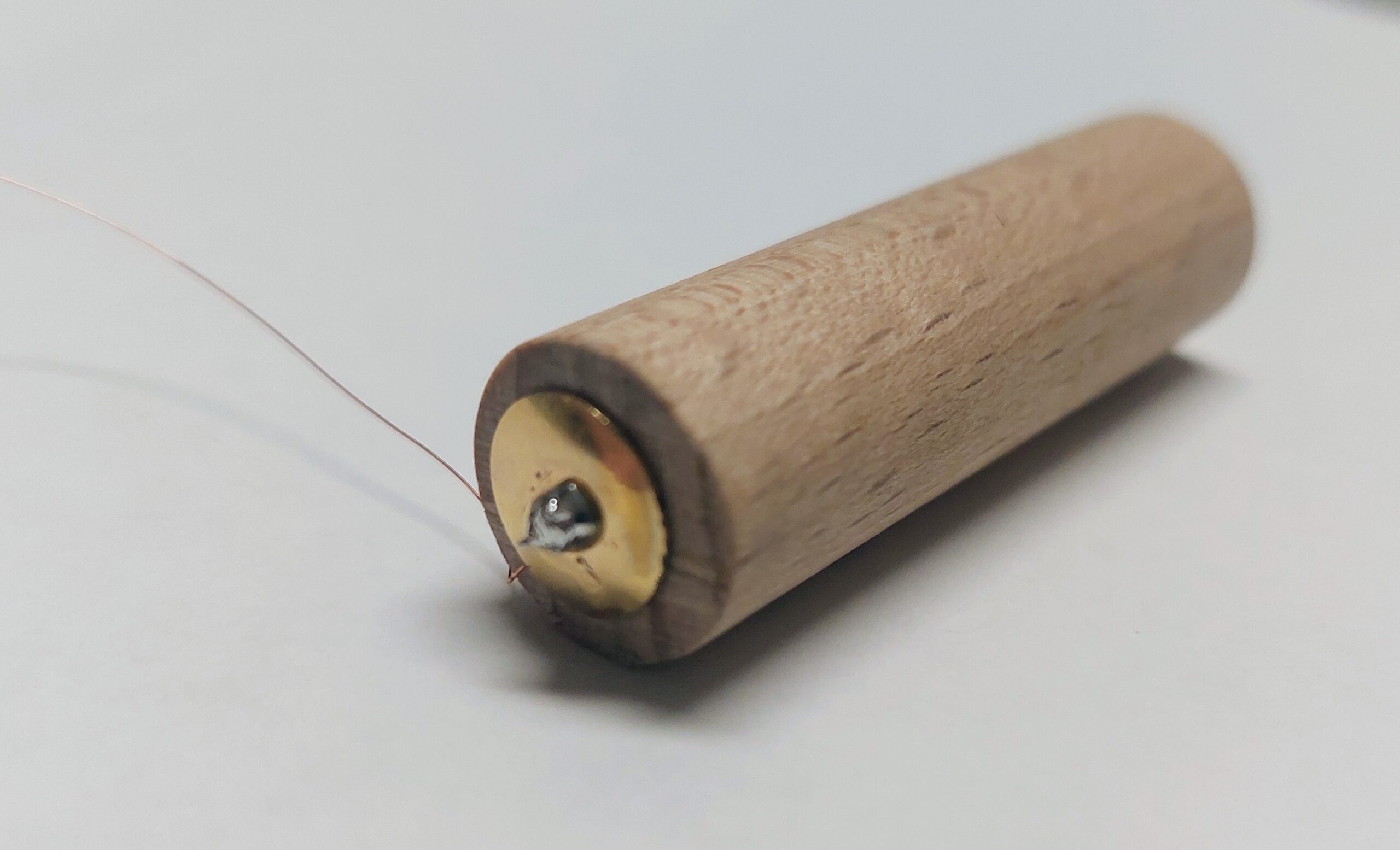
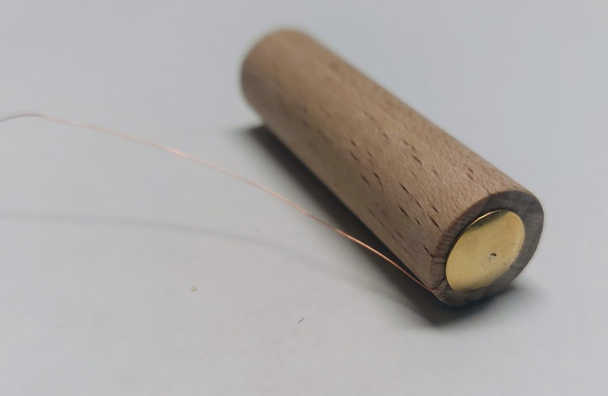
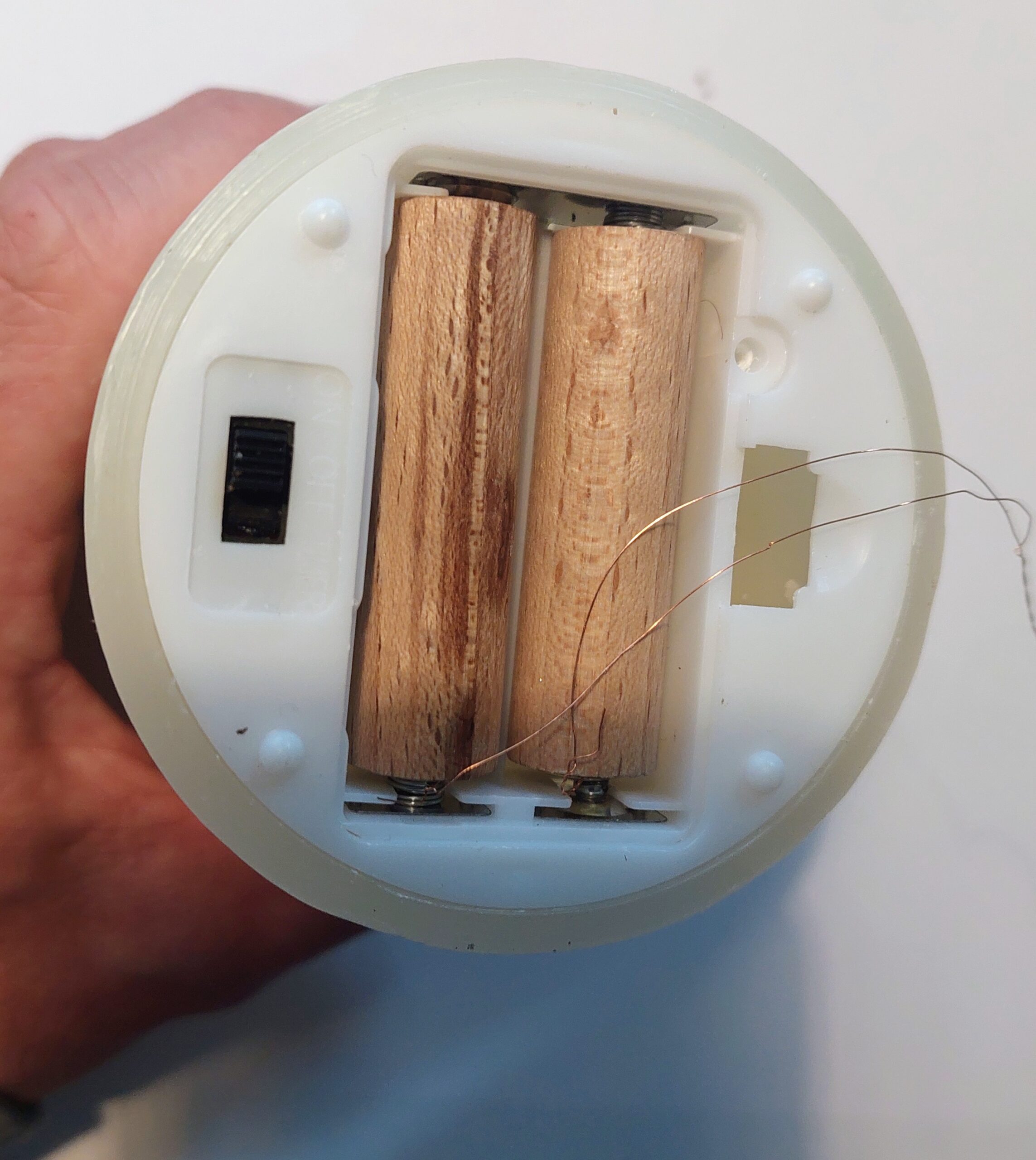
For these contacts, I used drawing pins, soldering enamelled copper wire1 to each pin before inserting them into the pre-drilled holes. The pins sit firmly, provide clean electrical contact, and keep the wiring secure. Once assembled, the wooden dummy fits smoothly into the candle’s battery compartment and offers a reliable external power connection without needing any batteries at all.
For very thin enamelled copper wire, a practical way is to twist it a few times to get a stable bundle, then burn off the insulation with a lighter and tin it afterwards. It takes some practice because the wire is fragile and the enamel does not always melt evenly, but once tinned it is much easier to solder.
Wiring and Voltage Calculation
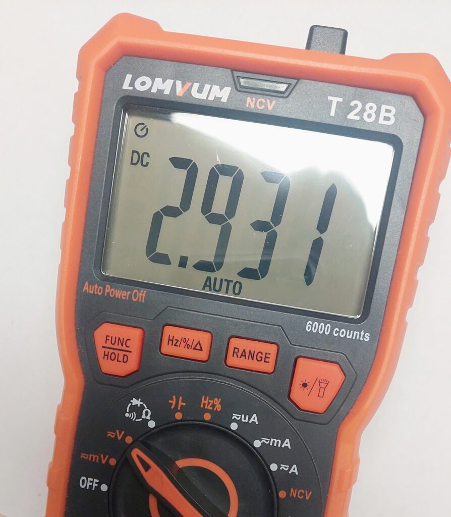
Each LED candle runs on 2 × 1.5 V AA batteries in series, giving 3 V. The D1 Mini GPIO pins supply 3.3 V, slightly higher than the candle’s rated voltage. To prevent stress on the LEDs, a small series resistor is recommended.
Calculation:
- Voltage difference: 3.3 V − 3.0 V = 0.3 V
- Estimated current per candle: ~8 mA
- Required resistor: R = V / I = 0.3 V / 0.008 A ≈ 37.5 Ω
With tolerance and availability in mind, a 47 Ω ±5% resistor in series with each candle is a clean and safe choice.
Wiring:
- Connect each candle’s positive lead to the resistor.
- Connect the other end of the resistor to a GPIO pin of the D1 Mini.
- Candle ground goes to the D1 Mini ground.
This allows safe switching of each candle while keeping the LEDs happy. With this setup, your candles are fully smart, individually controllable, and battery-safe.
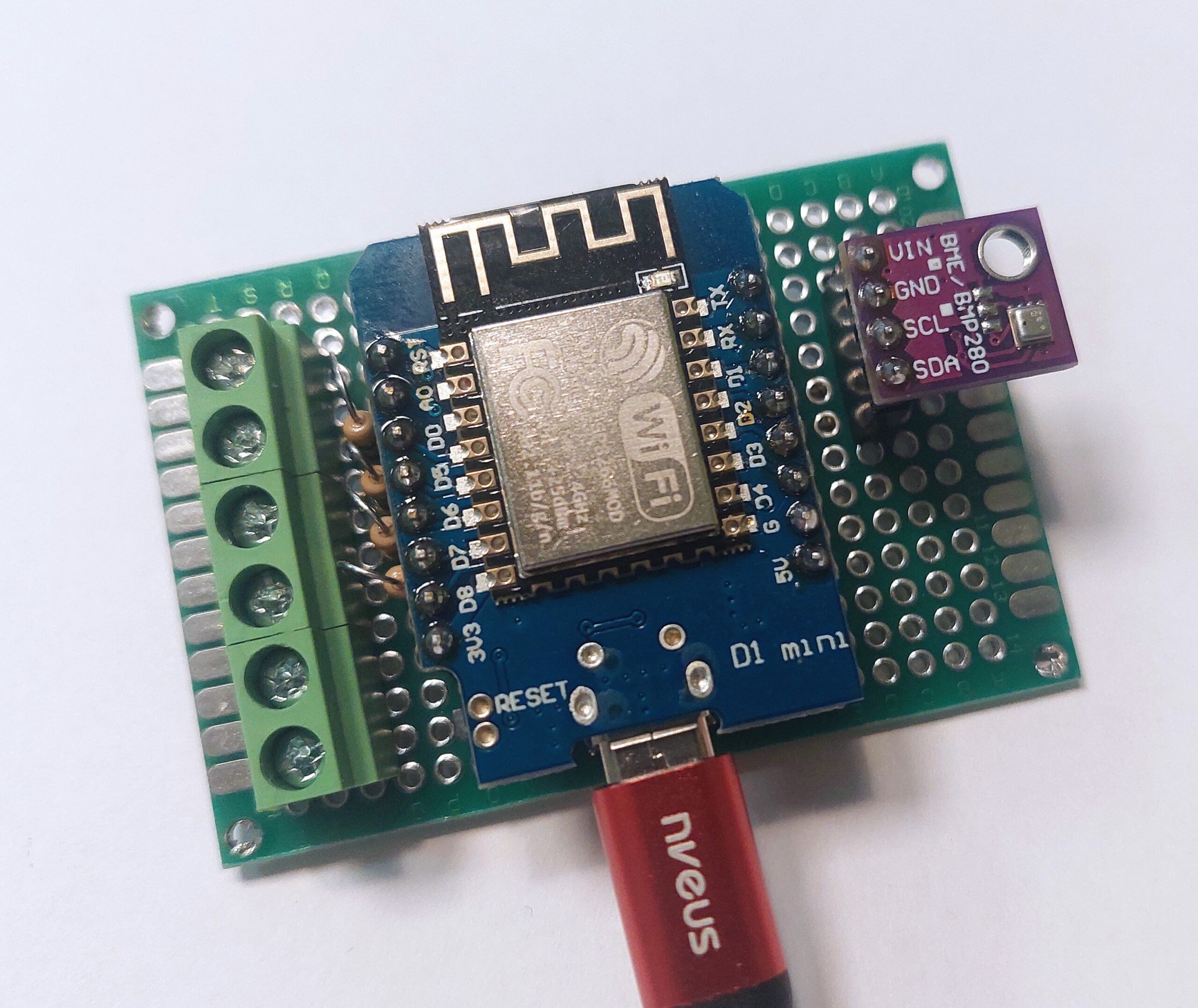
Wemos D1 Mini with Removable Female Headers and PCB Screw Terminal Blocks
For this build I used a Wemos D1 Mini (or a compatible clone) mounted on a custom PCB without soldering it permanently in place. Instead of fixing the microcontroller directly to the board, I used the included single-row female headers. These act as sockets, allowing the D1 Mini to be plugged in, removed, replaced, or upgraded at any time. This approach is especially useful during development, debugging, or future hardware revisions.
To keep the wiring flexible, I added 2-pin PCB screw terminal blocks. In this setup, a 6-port configuration is mounted on the side of the board. These terminals allow enamelled copper wires to be stripped, inserted, and secured with screws, eliminating the need for repeated soldering and making modifications quick and clean.
To maintain a compact and space-efficient layout, the D1 Mini is wired using only the pins located on the left physical side of the board: D0, D5, D6, and D7.
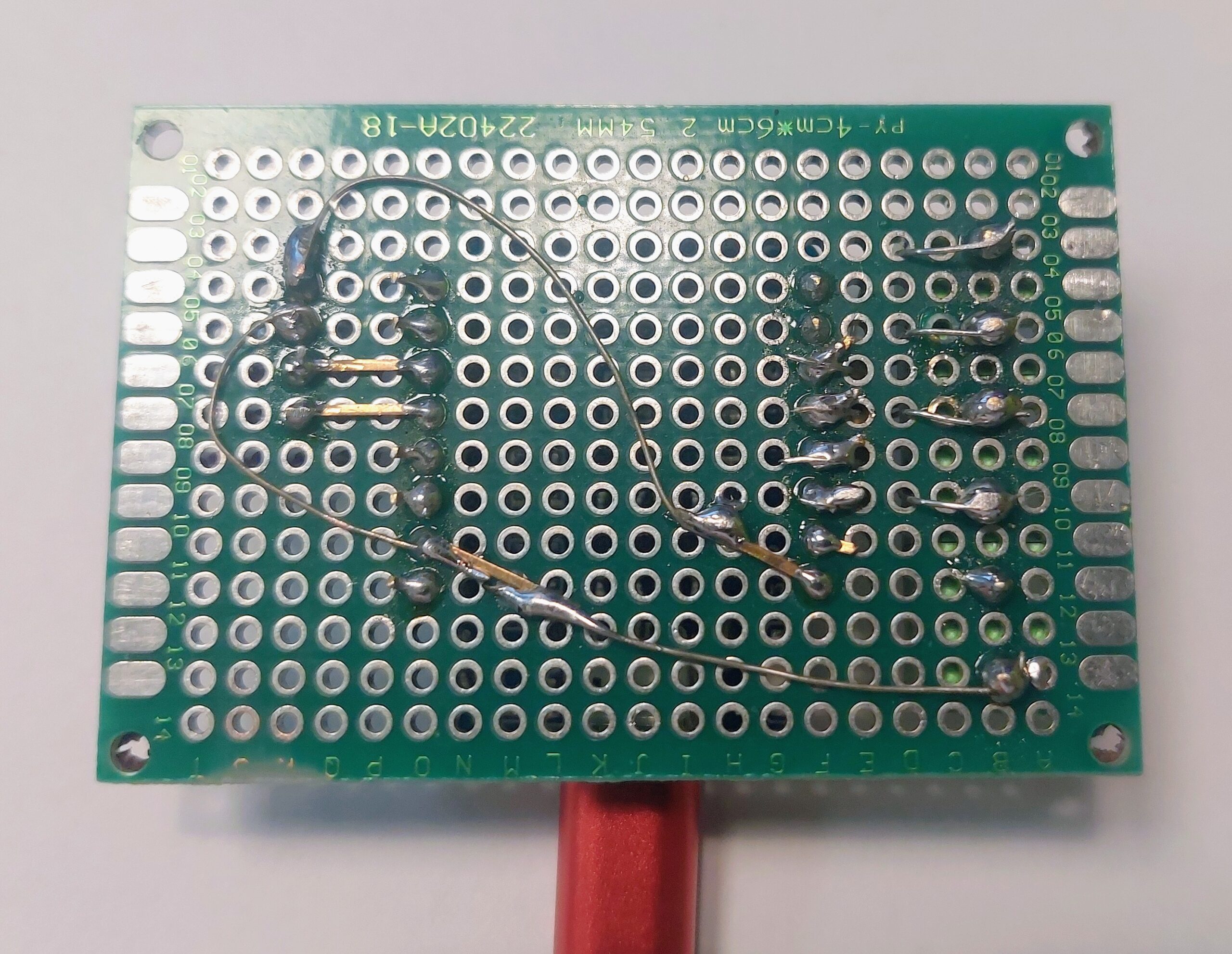
Additionally, resistors are placed between the GPIO outputs of the Wemos and the terminal blocks. They are inserted from the top side and soldered on the underside of the PCB. This provides proper current limiting while keeping the top side clean and all connections easily accessible.
For the second revision of the LED candle controller, I extended the hardware with environmental sensing. Since there was no temperature or humidity sensor installed in my office room, this version integrates a BME280 to measure temperature, relative humidity, and air pressure. The goal was to keep the PCB layout compact, minimize wire routing, and avoid occupying both sides of the Wemos D1 Mini unless absolutely necessary.
Note: The BME280 sensor is optional.
The controller works perfectly without it, and the sensor can be omitted entirely if environmental data is not required for the specific use case. If the BME280 is not used, simply remove or comment out the corresponding sensor block in the code. No further changes are required. The 3D-printed enclosure also supports this setup.
Custom PCB Case
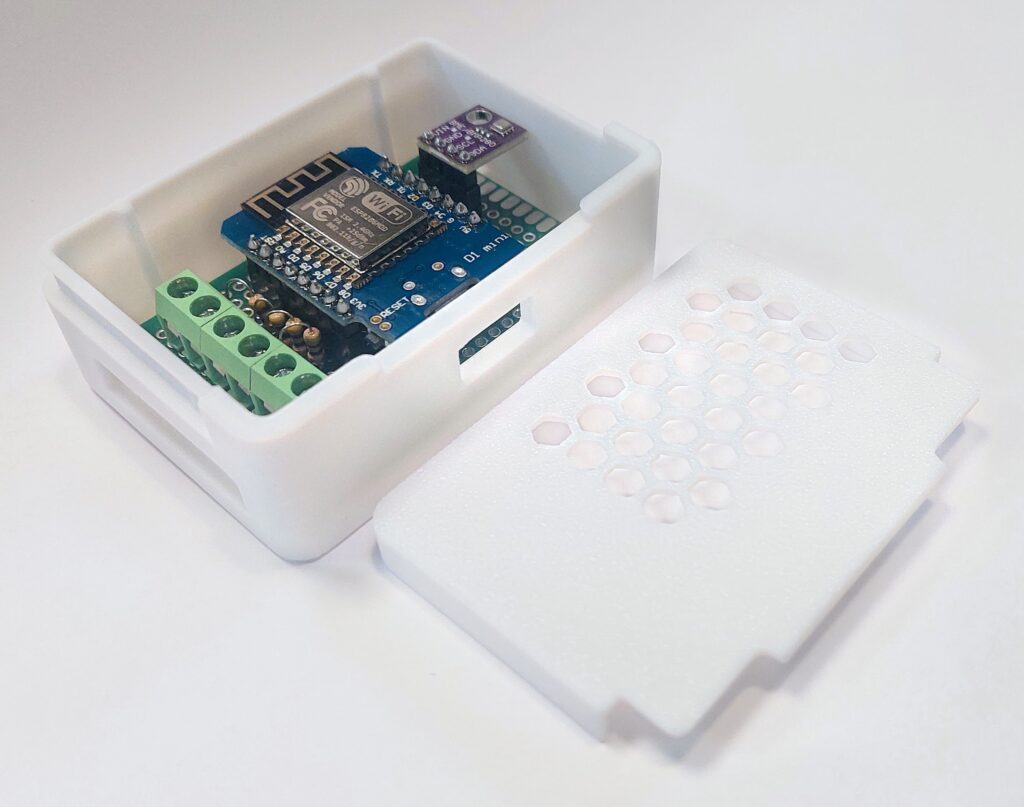
For this project, I designed a custom PCB enclosure based on the modular storage box system created by VINNIE3000. The original design is available on Printables and provides a highly flexible and parametric foundation for small electronics enclosures. Many thanks for the original design and the great work behind it.
Using the open source CAD software FreeCAD, I adapted the original model to fit the specific requirements of this project. The overall dimensions were adjusted to match the custom PCB layout, and dedicated PCB spacers with full surface support on all sides were added to ensure mechanical stability and proper alignment inside the case.
Openings were added for the Wemos D1 Mini USB connector (Micro-USB, pre-USB-C revision) as well as for the enamelled copper wire routing used for the LED candles. The goal was to maintain a clean external appearance while keeping assembly and maintenance straightforward. To ensure sufficient airflow and thermal stability, the top cover was modified with hexagon-style ventilation slots positioned above the main controller. A second top variant was also created for builds that include the optional BME280 sensor. In this version, the lid provides an additional cutout above the sensor area to prevent heat accumulation and to allow accurate environmental readings.
All modifications were designed to remain fully compatible with the original concept while tailoring the enclosure specifically to the needs of this project. The 3D-printable case files for this project can be downloaded here: Ambient Candles D1 Mini Case on Printables
ESPHome Code for Smart LED Candles
The ESPHome configuration for this project is straightforward. For a detailed explanation of the basic structure, check out my blog post on Smart Aquarium with ESPHome, where the setup, Wi-Fi, and general device configuration are covered.
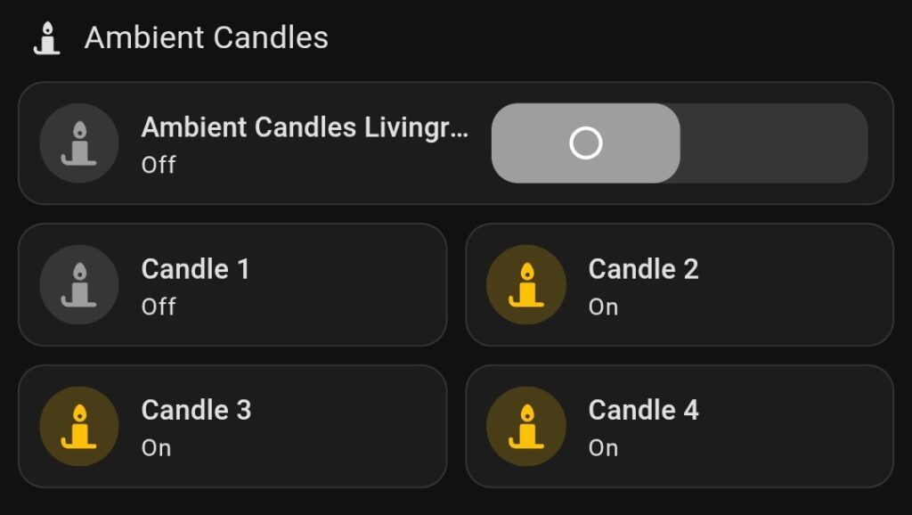
For the LED candle project, we only need to focus on the switch section, as each candle will be controlled individually via its GPIO pin. Using ESPHome switches makes it easy to turn each candle on or off from Home Assistant or any ESPHome-supported interface.
To add environmental metrics, a BME280 (I²C) sensor was introduced. It runs on 3.3 V only, so no regulator or level shifting is required when operating alongside the D1 Mini. SCL and SDA are routed to the right-side header pins to keep the signal path short and accessible:
| BME280 Pin | Connected To |
|---|---|
| VCC | 3V3 |
| GND | G |
| SDA | D2 (GPIO4) |
| SCL | D1 (GPIO5) |
Here’s the basic approach:
# BME280 I²C Sensor for ambient
i2c:
  sda: D2   # GPIO5
  scl: D1   # GPIO4
  # 3.3 V
  # GND
  scan: true

sensor:
  - platform: bme280_i2c
    address: 0x76
    id: bme280_sensor
    update_interval: 30s
    temperature:
      id: bme280_temperature
      name: "Ambient Air Temperature"
      oversampling: 16x
      icon: "mdi:thermometer"
    pressure:
      id: bme280_pressure
      name: "Ambient Air Pressure"
      icon: "mdi:gauge"
    humidity:
      id: bme280_humidity
      name: "Ambient Air Humidity"
      icon: "mdi:water-percent"

switch:
  - platform: gpio
    pin: D0   # GPIO16
    name: "Candle 1"
    id: led_1
    restore_mode: RESTORE_DEFAULT_OFF
    inverted: False
    icon: "mdi:candle"

  - platform: gpio
    pin: D5   # GPIO14
    name: "Candle 2"
    id: led_2
    restore_mode: RESTORE_DEFAULT_OFF
    inverted: False
    icon: "mdi:candle"

  - platform: gpio
    pin: D6   # GPIO12
    name: "Candle 3"
    id: led_3
    restore_mode: RESTORE_DEFAULT_OFF
    inverted: False
    icon: "mdi:candle"

  - platform: gpio
    pin: D7   # GPIO13
    name: "Candle 4"
    id: led_4
    restore_mode: RESTORE_DEFAULT_OFF
    inverted: False
    icon: "mdi:candle"
Each switch corresponds to a candle, allowing you full control over your smart Advent setup. You can integrate these switches into Home Assistant, create automation sequences, or even control the brightness with PWM if desired. This keeps the ESPHome configuration minimal while giving you full individual control of all four candles.
And the best part? You can now enjoy your Advent candles without ever fighting over who has to change the batteries. Santa would definitely approve of this smart, lazy – and slightly nerdy – approach to holiday cheer!
- TRU Components Enamelled copper wire N° 1567045 Outer: 1 x 0,15 mm, 220 m ↩︎