Antenna performance is one of the most critical factors in any Meshtastic or LoRa setup, especially when it comes to stable long-range communication. While node hardware often gets a lot of attention, the real-world results are typically dominated by antenna characteristics, tuning quality, and installation conditions.
A well-tuned 868 MHz antenna with roughly 5–6 dBi gain is generally a solid starting point for base station installations in the EU ISM band. This range offers a balanced radiation pattern that performs reliably in both relatively flat environments and mixed terrain, without introducing the trade-offs that come with very high-gain designs.
Gain Myth: Higher gain is not always better
High-gain omni antennas compress the radiation pattern vertically. This creates a flatter signal shape that works well on flat terrain, but can reduce coverage in hilly areas or when communicating with nearby nodes at different elevations.
More gain does not automatically mean more range.
Typical examples:
- 2–3 dBi → wider vertical coverage
- 5–6 dBi → balanced
- 8+ dBi → flatter radiation pattern
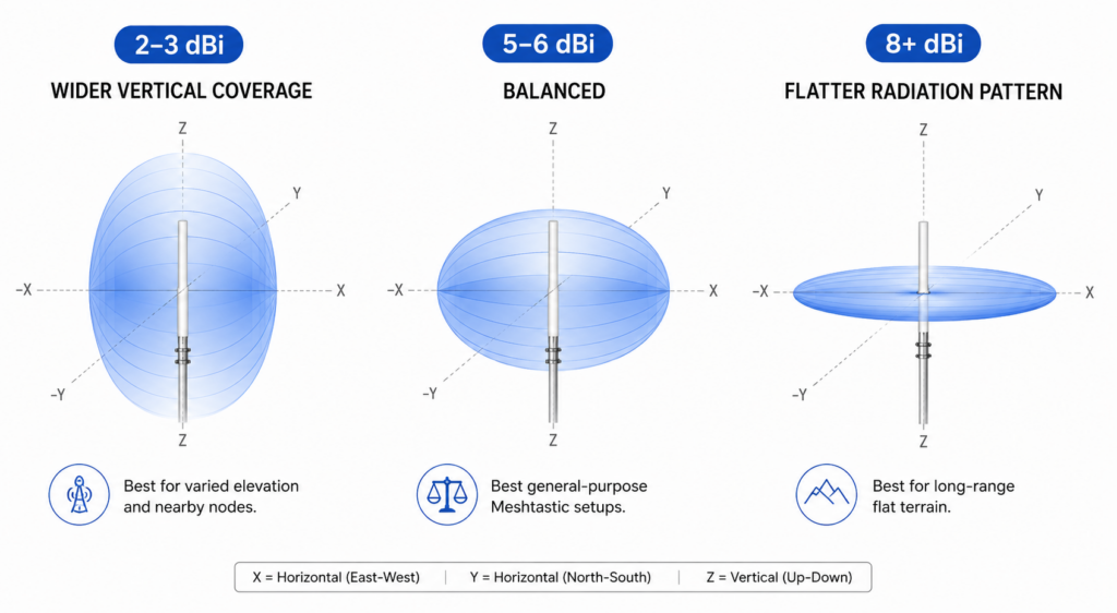
For many Meshtastic installations, 5–6 dBi is often a practical compromise.
Antenna placement
Even a high-quality antenna performs poorly when mounted incorrectly. Placement often has a larger impact than antenna gain itself.
Keep in mind:
- Mount antennas as high as practical
- Avoid placing antennas directly behind walls, metal roofs or solar panels
- Keep some distance from large metal objects
- Maintain vertical polarization for Meshtastic nodes
- Outdoor placement usually improves range significantly: A mediocre antenna mounted high outdoors often outperforms an expensive antenna mounted indoors.
Example Hardware Components for Antenna Installations
To give you a better understanding of suitable mounting hardware, here are two practical examples from WILTAnet GmbH. These components are commonly used in satellite and antenna installations and represent reliable, field-proven solutions. Press here
PremiumX 80cm Wall Mount with Support (Steel)
Product: PremiumX 80cm Wall Mount with Support Element (Galvanized Steel)
Manufacturer: WILTAnet / PremiumX
Item number: 119869
Link: View product on wiltanet.de
Summary:
This heavy-duty 80 cm wall mount is made from galvanized steel and designed for stable installation of satellite, DVB-T/T2, or LTE antennas. The integrated support element significantly improves structural rigidity, making it suitable for larger dishes up to 120 cm. The corrosion-resistant material ensures long-term outdoor durability.
Key Features:
- Galvanized steel construction (rust-resistant)
- 800 mm wall distance for optimal clearance
- Reinforced with additional support element
- Cable routing possible through open pipe design
- Easy installation with pre-drilled mounting holes
- Includes protective mast cap
PremiumX Double Mast Clamp
Product: PremiumX Double Mast Clamp (Mast Double Clamp)
Manufacturer: WILTAnet / PremiumX
Item number: 121254
Link: View mast clamps on wiltanet.de
Summary:
The PremiumX double mast clamp is designed to securely connect two antenna masts or pipes. It provides a stable and reliable fixation, especially useful for extending existing installations or reinforcing mounting setups. Its robust metal construction ensures durability in outdoor environments.
Outdoor Antenna Requirements
Outdoor antennas for Meshtastic installations need to be selected not only for RF performance but also for long-term environmental reliability. Since these antennas are continuously exposed to weather conditions, mechanical stress, and temperature fluctuations, physical durability is just as important as electrical characteristics.
Antenna housings and all external components must withstand rain, UV radiation, and wind without degradation over time. Equally important is proper sealing of all RF connectors and cable entry points, as moisture ingress is one of the most common causes of long-term signal loss in outdoor deployments.
Mounting stability also plays a critical role. Even small physical shifts caused by wind or weak mounting hardware can lead to inconsistent performance or detuning effects in practical use.
Key requirements:
- Weatherproof or IP-rated enclosure suitable for outdoor use
- Properly sealed RF connectors to prevent moisture ingress
- UV- and corrosion-resistant materials for long-term stability
- Mechanically stable mounting to prevent movement in wind
- Protected feedline entry points to avoid water intrusion
Example Hardware Components for Outdoor Antenna
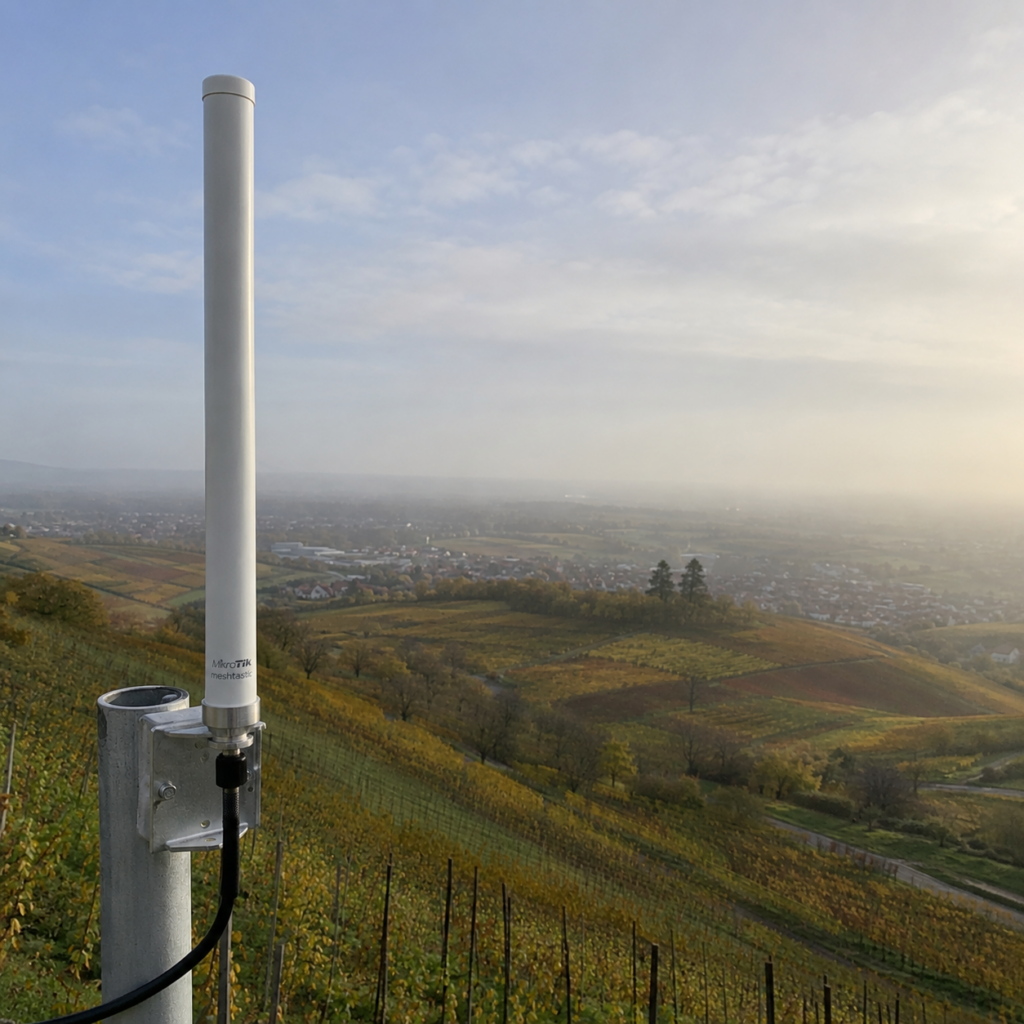
The MikroTik 868 Omni Antenna is an outdoor collinear antenna designed for the European 868 MHz ISM band, commonly used for LoRa, LoRaWAN and Meshtastic deployments. It is available through distributors such as Getic, where it is specified as a 6.5 dBi omni-directional antenna with IP66-rated housing and mast mounting support. Press here
MikroTik 868 6.5 dBi Omni Antenna
A key technical aspect of this antenna is its tuning range of 862–876 MHz, which aligns closely with the EU 868 MHz band, making it suitable for regionally compliant LPWAN installations.
Product page: https://www.getic.de/product/mikrotik-868-omni-antenna
Technical Specifications – MikroTik 868 Omni Antenna Kit
Datasheet: https://www.getic.de/files/catalogue/3805/868_omni_antenna_dsold-6965f307edb97.pdf
- Antenna type: Omni-directional collinear antenna
- Gain: 6.5 dBi
- Frequency range: 824 – 960 MHz
- Optimized band: 862 – 876 MHz (EU 868 MHz ISM band)
- Polarization: Vertical
- Impedance: 50 Ω
- Horizontal beamwidth: 360°
- Vertical beamwidth: 30°
- Connector: SMA
- Cable: Unfortunately, the manufacturer does not specify the exact cable type included in the package. MikroTik ships a 1 m RG58 cable with SMA male connectors on both ends.
- Mounting: Wall or mast mounting (25–50 mm mast compatible)
- Enclosure: Outdoor-rated, weather-resistant housing
- Protection rating: IP66
- Application: LoRa, LoRaWAN, Helium, Meshtastic networks
VSWR Performance
While MikroTik does not publish a full VSWR curve in the official datasheet, distributor specifications list a typical VSWR of ≤ 1.5 across the operating band.
Community measurements using NanoVNA equipment provide more practical insight:
- ~1.18 VSWR measured outdoors at 868 MHz
- ~1.44 VSWR measured in a less optimal indoor setup
These values indicate a very good impedance match at the target frequency and confirm that the antenna is properly tuned for the 868 MHz ISM band in real-world conditions.
Understanding VSWR and SWR
VSWR (Voltage Standing Wave Ratio) or simply SWR describes how well an antenna is matched to a specific frequency such as 868 MHz.
- A perfect match is: VSWR = 1.0
- The closer the value is to 1.0, the better the antenna transfers RF energy instead of reflecting it back into the radio.
This is especially important for Meshtastic and LoRa installations on 868 MHz.
Typical Values
| 1.0 – 1.3 | Excellent |
| 1.3 – 1.5 | Good |
| 1.5 – 2.0 | Acceptable |
| > 2.0 | Poor |
Many antennas are advertised as “868/915 MHz”, but they are not always properly tuned for the European 868 MHz band. Measuring VSWR with a NanoVNA or antenna analyzer helps verify real performance.
Exact Vertical Alignment of the Antenna
A correct vertical alignment of the antenna is especially important for Meshtastic. Most LoRa/Meshtastic antennas operate with vertical polarization and should therefore be mounted exactly upright.
Even a slight tilt can cause polarization losses and reduce the achievable range. This becomes even more important when using higher-gain antennas (for example 6.5 dBi or more), because they focus the signal more strongly in the horizontal plane and have a smaller vertical radiation angle.
A tilted antenna can therefore perform significantly worse, even if the antenna itself is technically good. A small spirit level placed directly on the antenna mast or housing is recommended to align the antenna precisely vertically.
Coax Cable Considerations
The coax cable between node and antenna is part of the RF path and has a direct impact on performance at 868 MHz. Even short runs introduce loss that reduces both transmit power and receive sensitivity.
Key factors to consider:
- Keep the cable as short as possible to minimize signal loss
- RG-58 is acceptable for very short indoor runs. LMR-200 or LMR-240 is preferred for lower loss, especially over longer distances
- Avoid unnecessary connectors, each one adds additional attenuation
- Prevent sharp bends to maintain stable signal quality
In many real-world setups, cable quality and length have more impact on range than small differences in antenna gain. It is also important to always check the manufacturer’s datasheet, because a higher-priced cable does not automatically guarantee lower loss at 868 MHz. Real attenuation depends on the specific cable design and frequency characteristics, and in some cases a cheaper or thinner cable can perform similarly or even better than a more expensive alternative if it is better matched to the operating frequency.
Coax Cable Loss Overview (≈ 868 MHz)
The following list provides a brief overview of cable types and their approximate dB loss values. It is intended as a general reference only and does not claim to be complete or fully comprehensive.
| Cable Type | Diameter | Loss (dB/m) | Practical Rating |
|---|---|---|---|
| RG174 | ~2.8 mm | ~1.0 – 1.3 | Very poor – only ultra-short pigtails |
| LMR100 | ~2.8 mm | ~0.9 – 1.1 | Very poor – avoid for anything longer |
| RG58 | ~5 mm | ~0.35 – 0.45 | Weak – acceptable for short indoor runs |
| LMR200 | ~5 mm | ~0.25 – 0.30 | Okay – short outdoor runs possible |
| H155 | ~5.4 mm | ~0.20 – 0.25 | Good mid-range – solid budget outdoor choice |
| LMR240 | ~6 mm | ~0.18 – 0.22 | Very good – recommended for mast setups |
| RG213 | ~10 mm | ~0.12 – 0.18 | Very good – robust and proven classic |
| LMR400 | ~10 mm | ~0.08 – 0.12 | Excellent – base station standard |
| Ecoflex 10 | ~10 mm | ~0.06 – 0.10 | Top tier – very low loss, premium setups |
Keep in mind that every additional connector in the RF path introduces a small amount of loss as well. As a rough guideline, a good-quality SMA connection typically adds about 0.1 to 0.3 dB of insertion loss per mated connector pair. While this is relatively small compared to cable losses over several meters, it can add up in setups with multiple adapters or extensions. For best performance, it’s generally recommended to keep the number of connectors as low as possible and ensure all connections are clean, tight, and properly seated.
Example Cable Choice for Outdoor Antenna Setup
For this installation, I decided to use a 3 m H155 cable with SMA male connectors on both ends. While a shorter cable would technically reduce signal loss slightly, I intentionally chose an additional meter to gain more flexibility during installation. Press here
This setup uses a pre-assembled H155 Low Loss 50 Ohm coax cable with SMA male connectors on both ends, manufactured by MCE Mauritz Electronics. The cable is available in multiple lengths, making it easy to adapt to different antenna positions and installation scenarios.
Technical details
- Cable type: H155 Low Loss
- Connector: SMA male to SMA male
- Available lengths: Multiple options available
- Selected length: 3 m
- Impedance: 50 Ohm
- Approximate attenuation: ~0.2–0.25 dB/m @ 868 MHz
- Estimated total cable loss: ~0.6–0.75 dB
- Practical rating: Good mid-range outdoor choice
For this installation, I intentionally selected the 3 meter version (Direct Link here), even though a shorter cable would technically reduce signal loss slightly.
The additional cable length allows the node enclosure to be mounted under the roof overhang, keeping it better protected from rain, direct sunlight and long-term weather exposure. Protecting the electronics was more important than saving the last few tenths of a dB.
With H155 at roughly 0.2–0.25 dB loss per meter, the additional meter only adds a small amount of signal attenuation. In this case, the tradeoff for improved weather protection and cleaner cable routing was absolutely worth it.
Weatherproofing the SMA Connection
The SMA connection between the antenna and the Meshtastic device should be protected against moisture, especially for outdoor installations.
Even small amounts of water can lead to corrosion, signal degradation, or connection problems over time.
A simple and reliable solution is to use self-amalgamating tape, which is available in almost every hardware store. Wrap the tape tightly around the SMA connector and cable connection so that it seals itself and forms a waterproof protective layer. Make sure the connector is clean and dry before applying the tape.
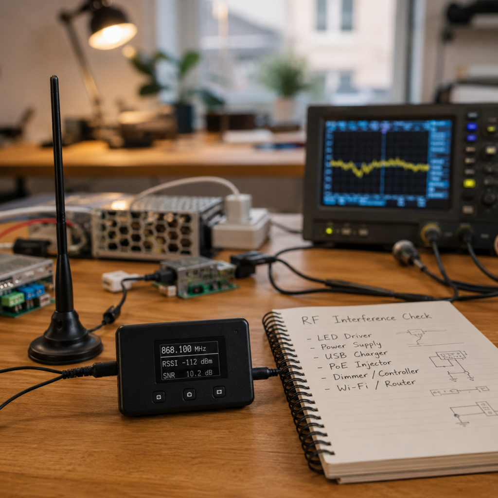
Cellular interference near LTE and 5G towers
Meshtastic nodes placed very close to cellular infrastructure, especially within roughly 300 m of LTE or 5G sites, may experience reduced receive sensitivity due to strong out-of-band RF energy, potentially impacting receiver performance.
Possible mitigation:
- Use cavity or SAW filters
- Increase distance from the antenna location if possible
- Verify receive performance using node statistics
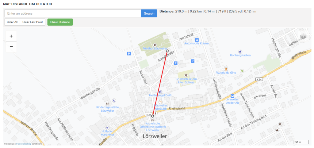
Nearby cellular infrastructure can affect reception much more than people expect. This does not mean 300 m is a strict limit, but in practice very close proximity to a tower increases the chance of RF overload effects, especially with simple or unfiltered receivers.
To check how close your node is to a mast, use a simple line-of-sight measurement tool: CalcMaps Distance Tool
If you are very close to a cellular tower and notice degraded reception, using a band-pass filter for 868 MHz (SAW/BAW type) can help reduce unwanted out-of-band energy and improve receiver stability. This is optional, but often useful in high-RF environments.
Effective Radiated Power (ERP), Antenna Gain and Cable Losses
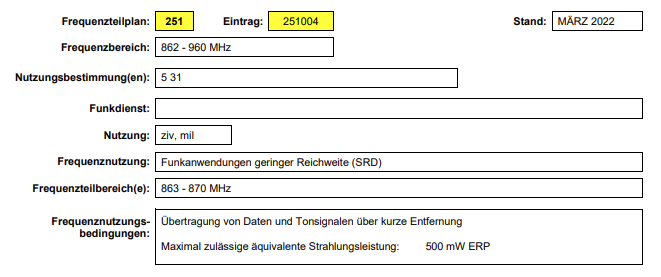
The 500 mW ERP limit defined in the German frequency allocations published by the Bundesnetzagentur (BNetzA) refers to the Effective Radiated Power. This is not simply the output power of the radio module, but the resulting radiated power after considering the complete transmission chain.
ERP describes the power that is effectively radiated by the antenna in its main direction compared to a theoretical reference antenna (a half-wave dipole).
In practice, ERP is determined by three main factors:
- Transmitter output power (TX power): the raw power generated by the radio module
- Antenna gain: increases effective radiation in a specific direction (given in dBi or dBd)
- Cable and connector losses: reduce power between the radio and the antenna due to attenuation in coaxial cables, connectors, and adapters
A simplified relationship is:
ERP ≈ TX Power + Antenna Gain − Cable Losses
A system can exceed regulatory limits even if the transmitter itself is low power, for example by using high-gain antennas with minimal cable loss. Conversely, long or lossy cable runs can significantly reduce the effective radiated power.
This is why compliance must always be evaluated at the antenna feed point, not only at the radio module output. The goal is to ensure that the total effective radiated power stays within the limits specified in the BNetzA frequency plan for the 868 MHz ISM band.
The official frequency allocations and band plans are published by the Bundesnetzagentur (BNetzA) and define which frequency ranges, power limits, and duty cycles are allowed for short-range devices in Germany. These documents are the authoritative reference for legal operation in the ISM bands.
Practical Takeaways
A well-performing Meshtastic or LoRa installation is rarely defined by a single component, but by the interaction of antenna quality, placement, and feedline losses. In most real-world scenarios, careful installation decisions have a larger impact on performance than small differences in hardware specifications.
Key points to remember:
- Antenna placement and height typically matter more than antenna gain alone
- A balanced 5–6 dBi antenna is often a reliable choice for general 868 MHz deployments
- Cable length and quality can significantly affect overall system performance
- Every connector introduces additional loss and should be minimized where possible
- Outdoor installations require proper weatherproofing and mechanically stable mounting
- High RF environments, such as proximity to cellular infrastructure, can influence receiver sensitivity and may require filtering or relocation
- Always consider the official BNetzA frequency plans and regulatory limits to ensure compliant operation within the 868 MHz ISM band
In practice, optimizing the overall system as a whole consistently yields better results than focusing on individual components in isolation., a VSWR close to 1.2 is considered excellent and indicates that the antenna is not just “label-compatible” with 868 MHz, but actually well tuned.