This project describes the design and construction of a DIY LoRa Yagi-Uda antenna for the 868/869 MHz frequency range. The goal is to create a low-cost, high-gain directional antenna that can be manufactured with simple components and a 3D printer.
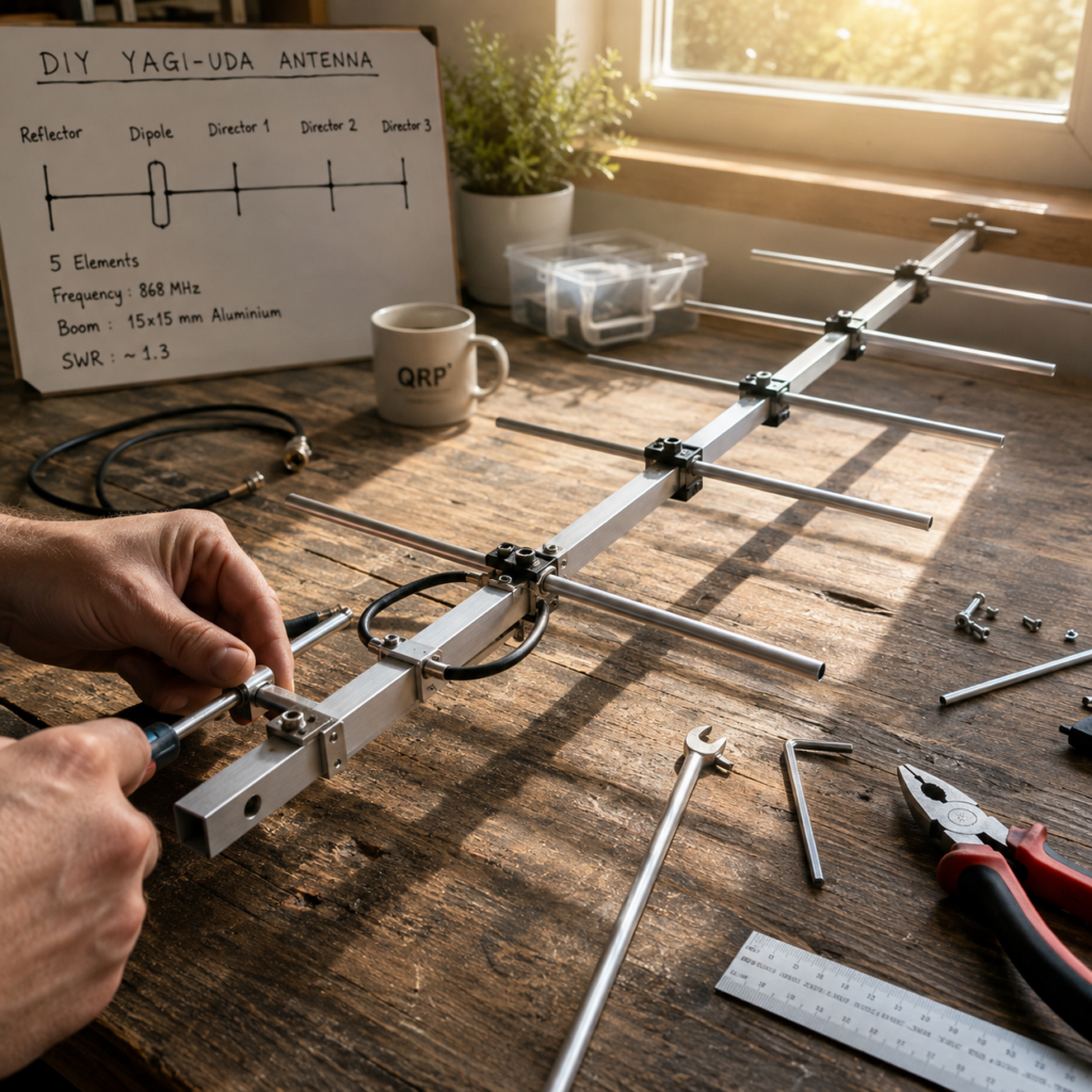
The motivation for building this antenna comes from a real-world interference problem. In my LoRa/Meshtastic setup, communication in the 868 MHz ISM band was affected by strong nearby LTE uplink signals. A standard omnidirectional antenna receives signals equally from all directions, including unwanted interference sources. To improve the signal quality, a different radiation pattern is required. A Yagi-Uda antenna provides a highly directional beam, increasing the desired signal strength while reducing reception from unwanted directions.
Special thanks go to Wolfgang (DK2FQ), an experienced amateur radio operator, who supported this project with his valuable advice, practical assistance, and extensive expertise in RF technology. His knowledge and guidance were a great help during the development and optimization of this DIY Yagi-Uda antenna.
Special thanks to Yannick (F1NSR) for designing and freely sharing these excellent 3D-printable models with the community. His work significantly simplified the mechanical construction of this antenna and made the project accessible to other radio enthusiasts.
Antenna Design and Calculation
The dimensions of a Yagi-Uda antenna are critical for achieving the desired performance at a specific frequency. The element lengths, spacing, and overall geometry directly influence the antenna impedance, gain, and radiation pattern.
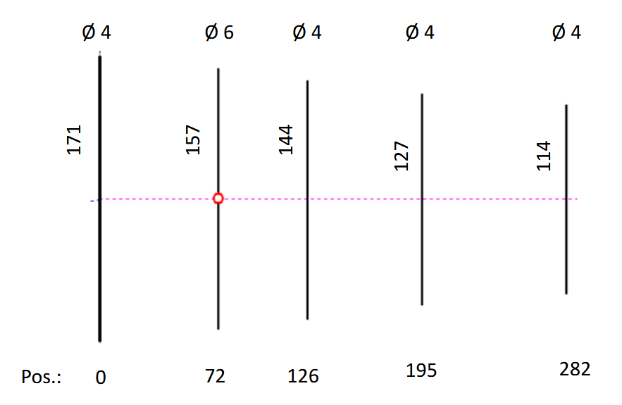
💭 Important: All element spacings are measured from the center of one element to the center of the next element. The diameter or thickness of the elements, such as 4 mm or 6 mm, does not affect these spacing measurements.
| Element | Type | Diameter | Length | Position | Center-to-Center Spacing |
|---|---|---|---|---|---|
| 1 | Reflector | 4 mm | 171 mm | 0 mm | – |
| 2 | Driven Element | 6 mm | 157 mm | 72 mm | 72 mm |
| 3 | Director 1 | 4 mm | 144 mm | 126 mm | 54 mm |
| 4 | Director 2 | 4 mm | 127 mm | 195 mm | 69 mm |
| 5 | Director 3 | 4 mm | 114 mm | 282 mm | 87 mm |
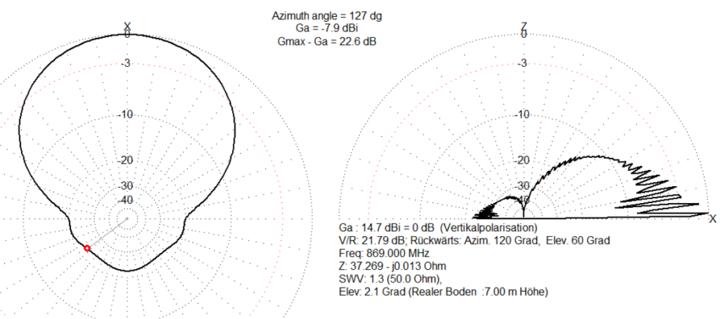
The following simulation was created for a 869 MHz Yagi-Uda antenna. While the radiation plots may look intimidating at first, only a handful of values are important when evaluating the antenna’s performance.
| Parameter | Simulation Result | What It Means |
|---|---|---|
| Frequency | 869.000 MHz | Design frequency of the antenna. Maximum performance is achieved near this frequency. |
| Forward Gain | 14.7 dBi | Indicates how strongly the antenna focuses energy in the desired direction. |
| SWR | 1.3 : 1 | Excellent impedance matching. Most transmitter power reaches the antenna instead of being reflected. |
| Front-to-Back Ratio | 22.6 dB | Signals coming from behind are attenuated by approximately 23 dB, helping reject interference. |
| Polarization | Vertical | The antenna should be installed vertically for best performance with vertically polarized signals. |
| Installation Height | 7 m above ground | The simulation includes realistic ground reflections at this mounting height. |
| Elevation Angle | 2.1° | The main beam is aimed almost parallel to the horizon, making it ideal for long-distance terrestrial communication. |
For a DIY Yagi-Uda antenna, these are excellent results and indicate an efficient, highly directional design suitable for long-range communication while minimizing interference from the rear.
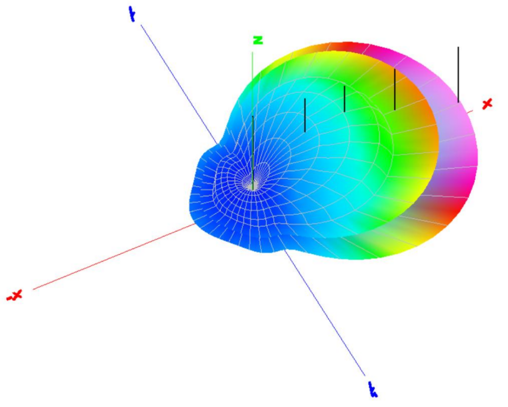
This 3D radiation pattern visualizes how the antenna concentrates RF energy in space. The large forward lobe represents the main direction of maximum radiation, while the much smaller rear lobe illustrates the antenna’s strong suppression of signals behind it. This highly directional pattern is one of the key advantages of a Yagi-Uda antenna, allowing more energy to be focused toward the intended target while reducing interference from unwanted directions.
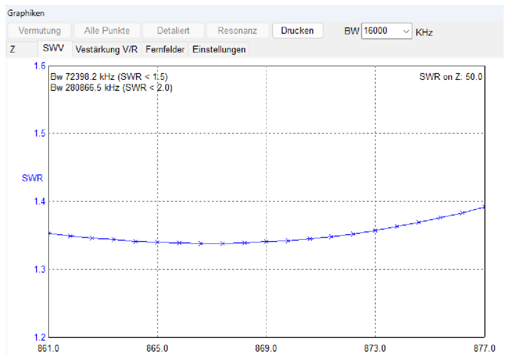
This graph shows the simulated Standing Wave Ratio (SWR) of the Yagi-Uda antenna across the frequency range from 861 MHz to 877 MHz. The antenna maintains an excellent impedance match, with an SWR remaining well below 1.5:1 across the entire ISM band. The minimum SWR of approximately 1.34:1 occurs close to the design frequency of 869 MHz, indicating efficient power transfer and minimal reflected energy. With an SWR < 1.5 over approximately 724 kHz, the antenna provides more than enough bandwidth for Meshtastic and other narrowband 868/869 MHz applications without requiring retuning.
💭 Design Note: A perfect 1.0:1 SWR is possible, but only at the cost of a lower front-to-back ratio. For this design, rear signal suppression is more important than perfect SWR, especially to reduce unwanted LTE uplink interference.
For this project, the complete antenna design was calculated by Wolfgang, DK2FQ, using specialized antenna simulation software. Based on the target frequency of 869 MHz, the software was used to determine the exact dimensions and positioning of the reflector, driven element, and directors.
Required Hardware Store Materials
💡 Note: The hardware store links provided are examples only and are not endorsements or advertisements. Equivalent materials can be purchased from other suppliers or hardware stores.
Aluminium Square Tube for Antenna Boom
The antenna boom is made from a lightweight aluminium square tube with a dimension of 15 x 15 x 1 mm. This profile provides a good balance between mechanical stability, low weight, and easy processing. The aluminium tube serves as the supporting structure for the Yagi-Uda antenna elements. The individual antenna elements can be mounted precisely along the boom while maintaining the required spacing for the 868/869 MHz design.
Aluminium was chosen because it is corrosion-resistant, easy to cut and drill, and widely available at low cost. With a length of 1 meter, the profile provides enough material for building the complete antenna structure while keeping the overall project inexpensive.
https://www.hornbach.de/p/vierkantrohr-alu-silber-15x15x1-mm-1-m/6069560
Aluminium Rods for Antenna Elements
The antenna elements are made from 4 mm diameter aluminium rods. These rods are used as the reflector and directors of the Yagi-Uda antenna and are cut to the required lengths according to the 869 MHz antenna design.
Aluminium was selected because it is lightweight, corrosion-resistant, easy to cut, and widely available at low cost. The 4 mm diameter provides a good mechanical balance between stability and RF performance, making these rods well suited for DIY Yagi antenna construction.
https://www.hornbach.de/p/rundstange-alu-natur-o-4-mm-1-m/8829172
Fasteners
Standard zinc-plated fasteners are inexpensive and work well, but they will eventually develop surface rust when exposed to the weather. For a durable outdoor installation, stainless steel or aluminium are the recommended choice. It offers excellent corrosion resistance, requires no maintenance, and keeps the antenna looking clean for years.
| Part | Fastener | Quantity | Note |
|---|---|---|---|
| Reflector Dipol Directors | Hexagon head bolts M4 × 25 mm Flat washers A4.3 Self-locking hex locknuts M4 | 7 | Mounting the Directors, Reflector, and Dipole to the Boom |
| Mast clamp | Countersunk head screws DIN 965 4×30 mm Flat washers A4.3 Self-locking hex locknuts M4 | 2 | Mounting the Mast Clamp to the Boom |
| Mast clamp | Hexagon head bolts M4 × 16 mm Flat washers A4.3 Self-locking hex locknuts M4 | 2 | Joining the Upper and Lower Mast Clamp |
Required 3D Printed Components
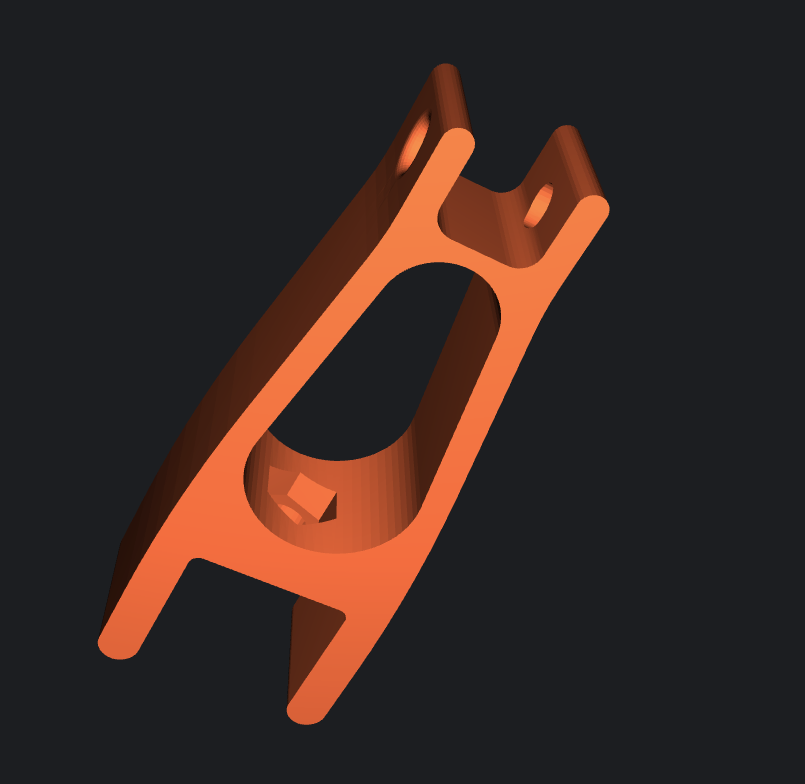
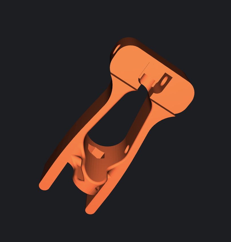
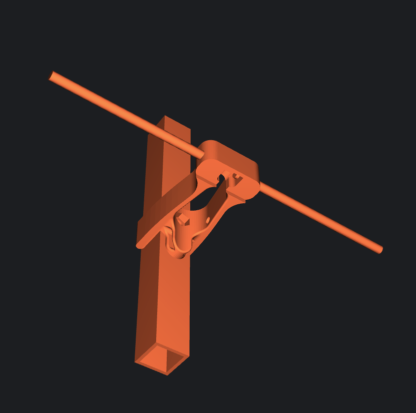
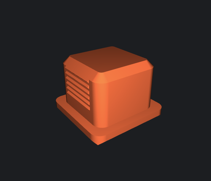
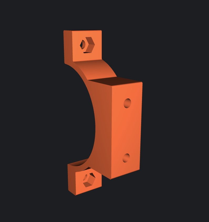
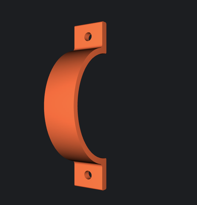
The following image provides an overview of all required 3D printed components for the antenna build. The shown parts come from different 3D model sources and are described in detail in the following sections, including their purpose, quantity, and installation location.
Yagi Element Clamps and Dipole
The antenna elements are mounted using dedicated 3D-printed clamps designed for a 15 × 15 mm aluminium boom and 4 mm diameter elements. The driven 6 mm diameter element (dipole) is also 3D printed and holds two brass elements, providing a mechanically stable and electrically isolated feed point for the coaxial cable.
The clamps ensure accurate and repeatable positioning of all elements along the boom, which is essential for achieving the expected antenna performance at 869 MHz. The models are printed from PETG, offering good mechanical strength and excellent weather resistance for outdoor installations.
The dipole requires careful assembly. Brass rods should be soldered using a high-temperature flux with minimal heating time to avoid damaging the printed part. It is also recommended to tin the coaxial cable braid before soldering to simplify the final assembly.
https://www.printables.com/model/1498968-yagi-antenna-clamps-and-dipole-for-23cm-or-869-or
Square Tube End Caps
To give the antenna boom a clean appearance and protect it from dirt and moisture, 3D-printed square tube end caps are installed on both ends of the aluminium boom. Besides improving the overall look, the end caps help prevent water, insects, and debris from entering the tube.
The original model is designed for 25 × 25 mm square tubes. Since this project uses a 15 × 15 mm aluminium boom, the model must be resized proportionally in the slicer until it fits the smaller profile. A uniform scaling of the entire model preserves the original geometry while ensuring a snug fit on the boom.
https://www.printables.com/model/494616-vierkantstopfen-square-plug-square-tubes/files
Pipe Clamp
The 50 mm pipe clamp is used to securely attach the antenna boom to the mast. In this project, the clamp is designed for a 50 mm diameter mast and provides a stable mechanical connection between the Yagi-Uda antenna and the mounting structure. The 3D-printed part allows the boom position to be fixed precisely while keeping the construction simple, lightweight, and cost-effective.
https://www.printables.com/model/466876-pipe-clamp-rohrschelle-50mm/files
Building the Dipole with the 3D-Printed Mount
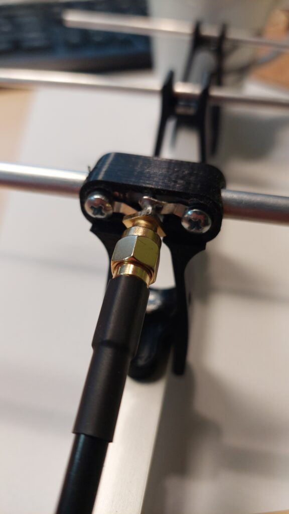
The dipole feed point uses a PCB-mount SMA connector.
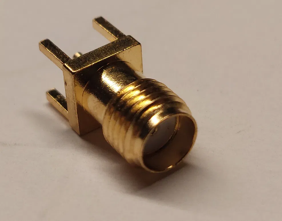
- Of the four mounting legs on the SMA connector, three are cut off, leaving only one ground leg.
- The remaining ground leg is soldered to a small spring, which is then soldered to one half of the dipole.
- The center pin (signal) of the connector is connected the same way: via a second spring, soldered to the other half of the dipole.
- Using springs here instead of a rigid solder joint allows for a bit of mechanical flex, preventing the connection from cracking due to vibration or stress on the boom.
- Each dipole half is fixed to the mount with a single screw.
- The mounting holes need to be slightly enlarged beforehand so the screws pass through cleanly without binding.
This gives a compact, mechanically stable feed point: the connector is rigidly mounted to the boom via the printed clamp, while the spring connections absorb minor movement between the connector and the dipole elements, reducing the risk of a fatigued or broken solder joint over time.
Assembly Instructions: Mounting the Elements on the Boom
- Start by mounting the third (last) director at the end of the boom – the square aluminum tube – with a few centimeters of clearance from the end. Attach it temporarily, e.g. with double-sided mirror mounting tape. Note: this is just for testing at this stage.
- Next, attach directors 2 and 1, the dipole, and the reflector at their correct spacing. A measuring jig is recommended for this. All spacings are measured from the center of one aluminum element to the center of the next.
- The setup can now be tested, ideally by measuring with a network/antenna analyzer (e.g. NanoVNA or similar).
- Using a pencil, mark the position of the printed mounts on the boom, on both the left and right side, to create reference points for the later drilling.
- Remove the elements/mounts again.
- It’s best to start again with the third director at the end of the boom. Set the first reference point here, again using the measuring jig and making sure it’s exactly centered.
- Center-punch the reference point to prepare for drilling.
- From there, work through director 2, director 1, the dipole, and finally the reflector, marking each reference point directly on the boom using the measuring jig. Background: all element mounts are identical, so the spacings are exact and consistent.
- Using a suitable drill bit – ideally with a drill press – drill the holes at the previously marked and center-punched positions. Tip: spray a bit of isopropyl alcohol on the drill bit for cooling; this prevents the material from smearing while drilling.
- Deburr the holes, then attach the individual elements. Tip: insert the screw into the element first and carefully press it into the recess using needle-nose pliers. Then place the element onto the boom and secure it with a washer and an M4 self-locking hex locknut.
- Mount the bracket on the opposite side the same way. Important: make sure the orientation relative to the mast accounts for the antenna’s intended polarization – in our case, vertical.
- For grip on the mast, you can use, for example, thin rubber cutlery/drawer liner or anti-slip mats.
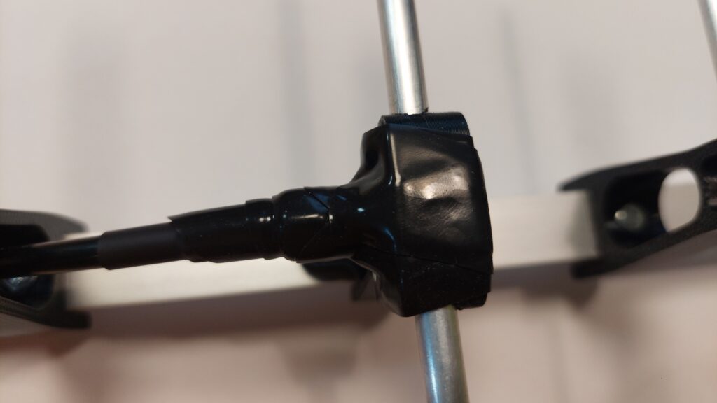
- The dipole can be sealed with self-fusing/self-vulcanizing tape (available at any well-stocked hardware store). Director and reflector elements can be fixed in place with a drop of suitable adhesive, e.g. industrial-strength glue.
- Done.
Weatherproofing the Connections
To protect the cable and connections from moisture, wrap them with self-fusing silicone tape. Unlike regular electrical tape, it bonds to itself as you stretch and wrap it, forming a seamless, watertight seal with no adhesive residue.
Adjusting Meshtastic TX Power for the Yagi Antenna
The Heltec V4 can transmit up to 27 dBm (~500 mW). But German regulations (BNetzA) limit the 868 MHz band to a maximum ERP of 500 mW, and this limit applies after antenna gain – so a directional antenna changes what TX power is actually allowed.
⚠️ Important: Minimum TX Power
Use only as much TX power as necessary to reliably reach the next node. This reduces interference and saves power.
As little TX power as possible – as much as necessary.
Our Yagi-Uda antenna has a measured Forward Gain of 14.7 dBi, corresponding to approximately 12.55 dBd. Add ~0.7 dB of loss from the 1 m RG-58/U cable.
At full power, ERP would be:
27 dBm − 0.7 dB + 12.55 dBd = 38.85 dBm ≈ 7.7 W ERP- far above the 500 mW limit.
To stay compliant, solve for the allowed TX power:
500 mW (26.99 dBm) − 12.55 dBd + 0.7 dB = 15.14 dBmSo the Heltec should be set to about 15 dBm. Using 15 dBm provides a small practical margin.
15 dBm − 0.7 dB + 12.55 dBd = 26.85 dBm ≈ 484 mW ERPsafely under the 500 mW limit.
Conclusion
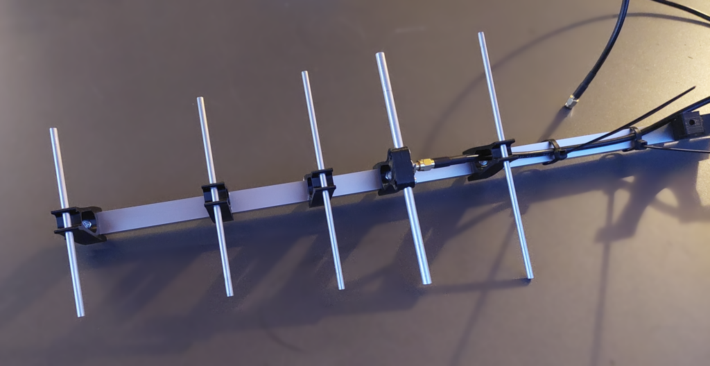
That’s it. A simple DIY Yagi-Uda antenna, a few 3D-printed parts, some inexpensive hardware, and a bit of RF theory can make a significant difference. I learned a lot while working on this project, especially about antenna design, RF, and the practical challenges that come with building your own antenna. I hope you have just as much fun building and experimenting with your own antenna.
73 and happy meshing!