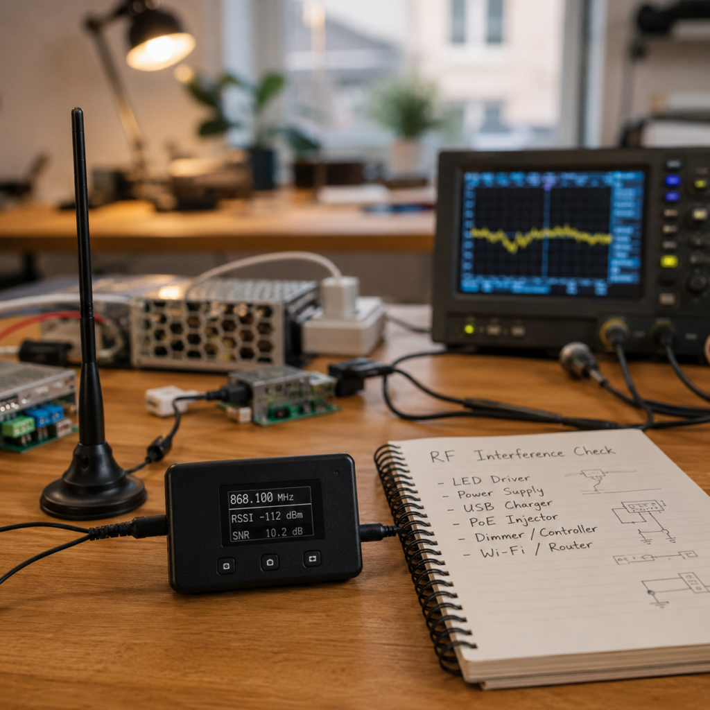
Meshtastic reception issues are often blamed on antennas, firmware, or node placement. However, in dense RF environments the actual problem can be interference from nearby transmitters.
Examples:
- LTE / 5G base stations: Relevant near EU868 because LTE Band 28 (~700 MHz) and Band 20 (~800 MHz) are relatively close to the 868 MHz LoRa band. Urban radio environments: Dense RF environments with many overlapping services such as FM radio (~88–108 MHz), cellular networks (~700 MHz–3.5 GHz), TETRA (~380–430 MHz), Wi-Fi (2.4 / 5 GHz), and various ISM devices.
- Multiple nearby transmitters: Several transmitters operating in the same area can increase the RF noise floor or overload receiver frontends, even if they use different frequencies.
- Telemetry systems for wind farms: Commonly use links around ~400 MHz, 868 MHz, 2.4 GHz, and licensed microwave backhaul systems (~6–38 GHz), depending on vendor and deployment.
- Strong RF sources within a short distance: High-power transmitters close to the antenna can reduce receiver performance, even when operating outside the LoRa frequency range.
- High-voltage power lines and transmission towers: Usually not a direct RF source at LoRa frequencies. Power grids operate at 50 Hz in Europe, but high-voltage infrastructure can generate broadband electromagnetic noise, corona discharge effects, and interference from nearby switching equipment. Substations and communication systems mounted on transmission infrastructure may have more impact than the power lines themselves.
In these situations, the issue is often not weak LoRa coverage. The receiver itself can become overloaded.
Typical technologies and interference sources with their commonly used frequency bands are listed below:
| Technology / Interference Source | Type | Frequency Bands / Range (EU / Typical) | Notes |
|---|---|---|---|
| GSM (2G) | Mobile Network | 900 MHz, 1800 MHz | Includes GPRS / EDGE |
| UMTS (3G) | Mobile Network | 900 MHz, 2100 MHz | Largely decommissioned in Germany |
| LTE (4G) | Mobile Network | 700 MHz, 800 MHz, 900 MHz, 1800 MHz, 2100 MHz, 2600 MHz | Main current cellular system |
| NR (5G) | Mobile Network | 700 MHz, 1800 MHz, 2100 MHz, 3.6 GHz | Core deployed bands in Germany |
| DECT | Cordless Telephony | 1880–1900 MHz | Phones, baby monitors |
| Wi-Fi 2.4 GHz | WLAN | 2400–2483.5 MHz | Highly congested ISM band |
| Wi-Fi 5 GHz | WLAN | 5150–5875 MHz | DFS channels may apply |
| Wi-Fi 6E | WLAN | 5925–6425 MHz | New 6 GHz band |
| Bluetooth / BLE | WPAN | 2400–2483.5 MHz | Frequency hopping system |
| Zigbee | Smart Home Mesh | 2400–2483.5 MHz | Shares band with Wi-Fi |
| Thread | Smart Home Mesh | 2400–2483.5 MHz | Used by Matter |
| Z-Wave | Smart Home Mesh | 868.4 MHz, 869.85 MHz | Sub-GHz EU band |
| Homematic IP | Smart Home | 868 MHz | Sub-GHz automation |
| EnOcean | Smart Home | 868 MHz | Energy harvesting systems |
| KNX RF | Building Automation | 868 MHz | Building control systems |
| Meshtastic / LoRa | LPWAN | 868 MHz | EU SRD-Band / ISM-Anwendung |
| RFID / NFC | Identification | 13.56 MHz | Short-range coupling |
| 433 MHz Devices | SRD | 433.05–434.79 MHz | Remotes, sensors |
| Switching Power Supplies | EMI Source | ~20 kHz–1 GHz+ (harmonics) | Broad-spectrum noise source |
| LED Drivers | EMI Source | ~20 kHz–several MHz | Switching noise |
| PV Inverters | Power Electronics | ~150 kHz–30 MHz | Grid-tied inverter noise |
| Powerline Communication (PLC / dLAN) | Data over power lines | 2 kHz–30 MHz | Conducted RF noise |
| Microwave Ovens | RF leakage | 2.45 GHz | Strong 2.4 GHz interference |
| Wind Turbine Telemetry | SCADA / RF Links | ~400 MHz, ~800 MHz, ~2.4 GHz | Depends on vendor and deployment |
| USB 3.0 Devices | Digital EMI | Noise around 2.4 GHz | Affects Wi-Fi / Bluetooth |
| EV Chargers (Wallboxes) | Power Electronics | kHz–MHz range | EMI depends on design |
| High Voltage Power Lines | Corona discharge | kHz–MHz range | Weather-dependent noise |
| Automotive | Keyless Entry (Europe) | 433.92 MHz | Common for remote locking/unlocking and passive keyless systems |
| Automotive | Passive Key Detection | ~125 kHz | Low Frequency (LF) proximity detection between vehicle and key |
| Automotive | Ultra Wideband (UWB) | 6–8.5 GHz | Used by newer vehicles for precise distance measurement and anti-relay protection |
Problem
Modern Meshtastic devices may use highly sensitive receiver front-ends and additional components such as an LNA (Low Noise Amplifier) to improve reception.
This is usually beneficial:
- improved sensitivity
- weaker signals become receivable
- lower packet loss
But in high RF environments, there can be unwanted side effects:
- receiver desensitization
- increased noise floor
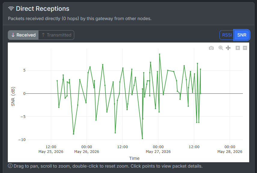
- unstable SNR values
- packet loss
- reduced effective range
Instead of amplifying only the desired LoRa signal, the receiver may also amplify unwanted nearby RF signals.
Typical symptoms:
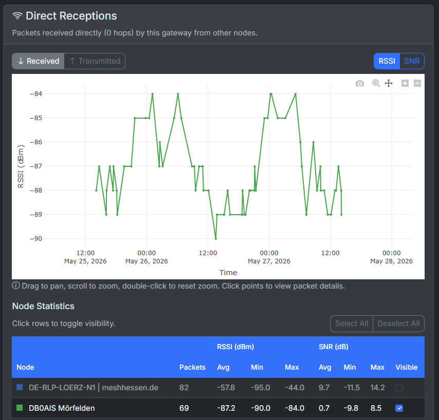
- RSSI appears normal
- SNR fluctuates heavily
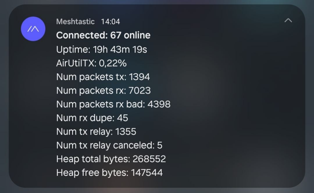
- Extremely high number of bad packets, while channel utilization remains very low
- nodes randomly appear or disappear
- unstable reception quality
Channel Utilization in Meshtastic
Channel Utilization in Meshtastic indicates how busy the LoRa channel currently is. It represents the percentage of airtime occupied by received transmissions and interference on the selected frequency.
Typical Values
These values are practical guidelines rather than official Meshtastic thresholds.
| Channel Utilization | Interpretation |
| 0 – 5 % | Very low utilization |
| 5 – 15 % | Normal utilization |
| 15 – 40 % | Increased channel activity |
| Above 40 % | Possible packet collisions and communication issues |
High Channel Utilization can lead to delayed transmissions, packet loss, and reduced network reliability.
Solutions
Before changing hardware:
- verify antenna quality
- check cable and pigtail losses
- test a different installation location
- avoid direct exposure toward strong transmitters
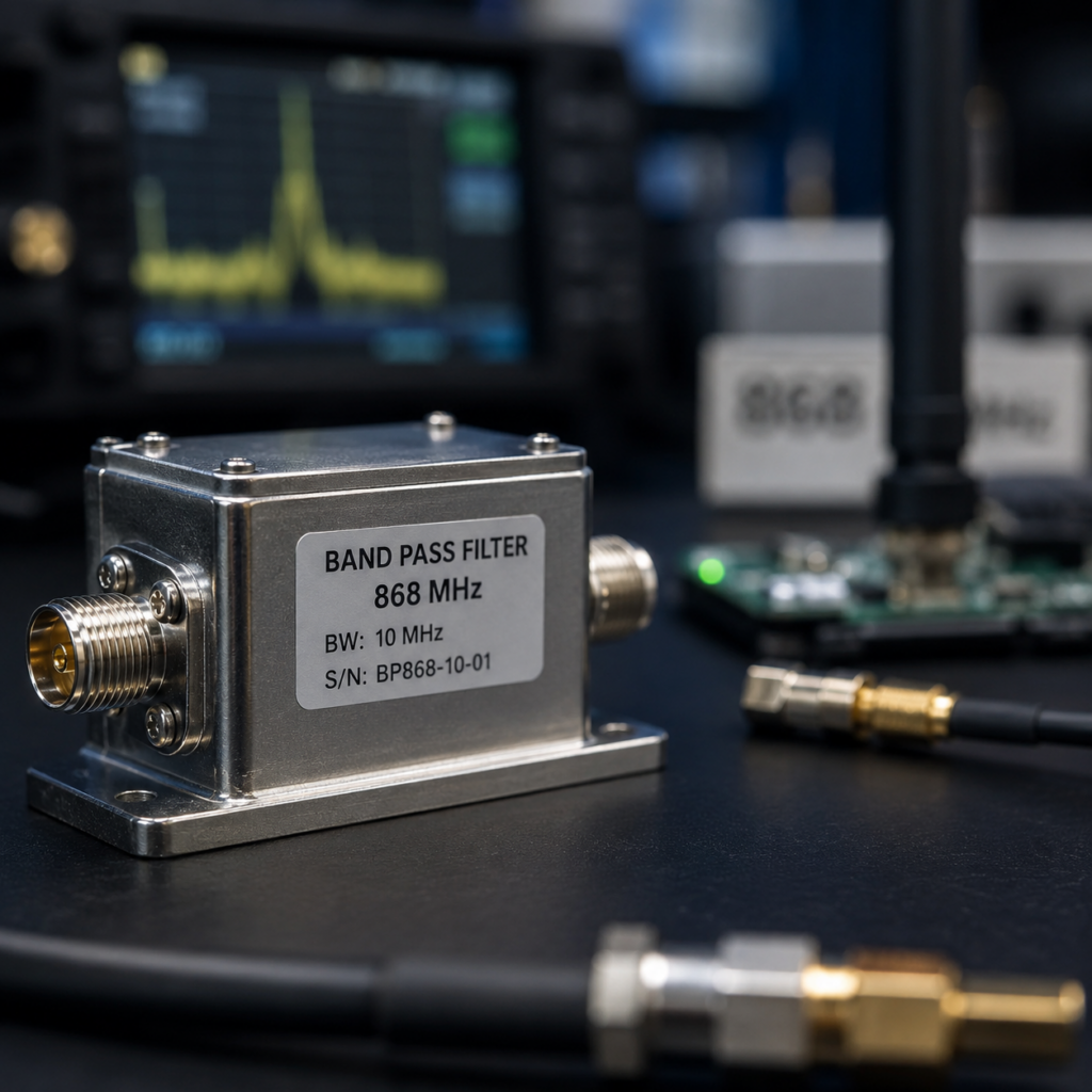
If interference remains unavoidable, filtering can help.
Goal:
Remove unwanted RF energy before it reaches the receiver.
RF Filter Types for LoRa 868 MHz (Practical Ranking)
| Rank | Technology | Description | Advantages | Disadvantages | Typical Rejection | Insertion Loss | Typical Use / Recommendation |
|---|---|---|---|---|---|---|---|
| 1 | LC Filter | Inductors + capacitors forming basic RF filter | Very cheap, simple, easy to integrate | Low selectivity, strongly tolerance-dependent, weak against strong signals | Low | ~0.5–2 dB | Only for light interference or basic tuning, not for LTE proximity |
| 2 | PCB / Microstrip Filter | Filter structures directly on PCB traces | Low cost, compact, integrated | Performance depends heavily on layout, weak out-of-band suppression | Low–Medium | ~1–3 dB | Integrated IoT devices, not suitable as external RF fix |
| 3 | Ceramic Filter | Ceramic resonator-based filtering | Compact, stable, slightly better than LC | Limited selectivity, less common in modern 868 MHz RF frontends | Medium | ~1–2 dB | Embedded systems, moderate interference environments |
| 4 | SAW (Surface Acoustic Wave) | Piezoelectric substrate converts RF to acoustic waves | Best cost/performance ratio, small, widely available | Limited power handling, can be overloaded by strong LTE signals | Medium | ~1–3 dB | Standard LoRa/Meshtastic setups, urban interference environments |
| 5 | Helical Filter | Coil-based resonator in shielded housing | Higher selectivity than SAW, good robustness | Larger size, more expensive, still not extreme rejection | High | ~1–2 dB | Strong RF environments, mobile/ham radio setups |
| 6 | Cavity Filter | Tuned metal resonant cavities | Excellent rejection, very strong LTE/5G suppression | Expensive, large, heavy | Very High | ~0.3–1 dB | Best choice for dense RF / nearby LTE towers (your case) |
LTE Uplink Interference
Frequency Allocation Overview (BNetzA – LTE 800 vs. 868 MHz ISM)
| Frequency Plan | Entry | Frequency Range | System | Direction | Filter Behavior (868 MHz Bandpass) |
|---|---|---|---|---|---|
| 250 | 250003 | 791–821 MHz | LTE Band 20 | Downlink (Base station → UE) | Strong attenuation (reject band) |
| 250 | 250005 | 832–862 MHz | LTE Band 20 | Uplink (UE → Base station) | Strongest attenuation (critical reject band) |
| 251 | 251004 | 863–870 MHz | SRD band / ISM applications (LoRa, Meshtastic) | Bidirectional | Passband (low insertion loss required) |
Practical Interpretation for an 868 MHz Bandpass Filter
A properly designed 868 MHz ISM bandpass filter should:
Reject (block)
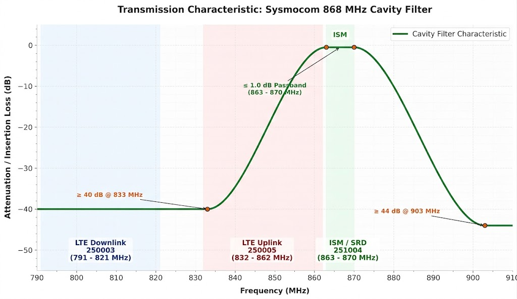
- 791–821 MHz → LTE downlink signals from base stations
- 832–862 MHz → LTE uplink signals from nearby mobile devices (often the strongest interference source)
Pass (allow)
- 863–870 MHz → ISM / SRD band used by Meshtastic, LoRa, Sigfox, etc.
Sysmocom 868 MHz Bandpass Cavity Filter
| Parameter | Specification | Description |
|---|---|---|
| Product | 868 (863..870) MHz Cavity Filter (ISM, LoRa, SigFox, Helium) | |
| Manufacturer | sysmocom | |
| Product Link | sysmocom 868 MHz Cavity Filter | |
| Filter Type | Bandpass Cavity Filter | |
| Frequency Range | 863–870 MHz | Passes signals within the 868 MHz ISM band |
| Applications | LoRa, SigFox, Helium, Meshtastic | |
| Insertion Loss | ≤ 1.0 dB | Signal loss caused by the filter. Lower values mean less reduction of the wanted signal |
| Passband Ripple | 0.2 dB | Variation of signal loss within the allowed frequency range. A lower value means a more consistent signal transmission across the entire band |
| Rejection | ≥ 40 dB @ 833 MHz, ≥ 44 dB @ 903 MHz | Specifies the attenuation at defined frequencies outside the passband. Higher rejection values indicate stronger suppression of out-of-band signals |
| VSWR | ≤ 1.25 | Indicates the impedance matching of the filter to a 50 Ω RF system. A low VSWR means minimal signal reflection at the filter connection |
| Impedance | 50 Ω | Standard RF impedance for antennas and radio equipment |
| Maximum RF Power | 30 W average RF power | Maximum continuous transmit power the filter can handle without damage |
| Connectors | SMA Female | RF connection type. Check the connector type of your radio and antenna. An SMA adapter or SMA gender adapter may be required depending on the hardware used |
| Temperature Range | -10 to 50 °C | Allowed operating temperature range |
| Dimensions | 54 × 54 × 45 mm | |
| Weight | 220 g | |
| Protection Rating | IP50 (not suitable for outdoor use) | Not suitable for unprotected outdoor installation; no protection against water. |
Filter Installation Direction
The installation direction of the cavity filter is not always intuitive and is often not clearly explained in product descriptions.
The filter connectors are marked as follows:
- IN: Connect this side to the Meshtastic node (radio device).
- OUT: Connect this side to the antenna.
The filter is installed between the radio module and the antenna. For a passive cavity filter, the direction is generally not important unless the manufacturer specifies otherwise. It helps to suppress unwanted signals before they reach the receiver input of the Meshtastic node.